Systems to Control Nitrogen Oxides (NOx) in Coal Fired Power Plants
By Prasanna Seshadri
Commonly referred to as NOx, Nitrogen oxides are one of the primary pollutants emitted by high temperature combustion systems such as pulverized coal (PC) fired boilers. Due to its role in both acid rain and ozone formation, NOx is a regulated pollutant under the EPA’s Clean Air Act. The options to reduce NOx emissions include source reduction and post combustion treatment of the flue gas. To control NOx at source, fuel and air distribution, otherwise referred to as staging, are modified to reduce flame temperatures. This is typically achieved by using low NOx burners.
Post combustion measures for NOx control include both catalytic (SCR) and non-catalytic (SNCR) where NOx in the flue gas is reduced to molecular Nitrogen by reaction with Ammonia. However, it is quite common for utilities and other industrial combustion systems to employ both source reduction and flue gas treatment to meet required regulations. This paper will particularly focus on the two tail end options, SCR and SNCR, for flue gas NOx control.
1. Introduction
Nitrogen oxides (NOx) denote the combined emissions of nitric oxide (NO), nitrogen dioxide (NO2) and other nitrogenous species in combustion derived flue gas. While NOx comprises all oxygenated nitrogen species, NO is the most dominant species in combustion gases accounting for anywhere between 95-99% of the total NOx in the gas stream. Together with SOx and Particulate Matter (PM), NOx is strictly regulated. NOx contributes to the formation of smog and acid rain, as well as increasing the amount of ozone (O3) in the earth’s troposphere. When NOx and volatile organic compounds (VOCs) react in the presence of sunlight, they form photochemical smog, which is a significant form of air pollution. The high concentrations of ozone in the atmosphere typically arise from high NOx emissions together with other reactive hydrocarbons, termed as VOCs. At lower levels, ozone is created by a chemical reaction between nitrogen oxides (NOx) and VOCs in the presence of heat and sunlight. Production of O3 follows the chain reaction mechanism as follows7:
NOx + VOCs + Sunlight → O3 + other products (1)
NO2 + hν → NO + O(3P), λ<400 nm (2)
O(3P) + O2 → O3 (3)
Peroxy-radicals (HOCO) in the atmosphere, produced as a result of carbon monoxide (CO) oxidation with the hydroxyl radical OH, go on to react with NO to produce NO2, which is then photolysed by UV-A radiation to give a ground-state atomic oxygen. This further reacts with molecular oxygen to form ozone7. While NOx emission limits vary globally, the U.S has one of the strictest limits in the world, especially for existing coal power plants. For new installations, the limits are even more stringent requiring the use of Best Available Control Technology (BACT) in both attainment and non attainment areas. Selective Catalytic Reduction, referred to as SCRs, is the current BACT for NOx control in power plants and also for other industrial applications. NOx is also regulated in combustion engine vehicles, especially vehicles using diesel engines.
2. Nitrogen Oxides (NOx) from Fuel Combustion
Typically, NOx formation happens during fuel combustion through two major pathways. In the first case, Nitrogen present in combustion air reacts with oxygen forming Nitrogen Oxide species. This is referred to as Thermal NOx and is a result of high combustion temperatures. The other major source of NOx is fuel NOx which is the result of fuel Nitrogen reacting with the oxygen in combustion air. Unlike thermal NOx, fuel NOx formation can happen at much lower gas temperatures. Fuel NOx is a significant contributor especially in coal power plants and can account for over 50% of the overall amounts of NOx generation. The control of NOx in combustion derived flue gas usually involves a two-phased approach – during fuel combustion and post treatment of flue gas. The primary focus of combustion control is to minimize thermal NOx formation and the latter option is to reduce the overall amount of already formed NOx.
3. Control Techniques
3.1. At Source Reduction
With the development of advanced burner technologies, NOx control begins with fuel combustion. Low NOx burners are designed to reduce the overall combustion temperature, thereby reducing the total amount of thermal NOx. Low NOx burners control fuel and air mixing to create larger and more branched flames. They accelerate fuel ignition and intensify combustion by achieving fuel rich conditions in the burner zone1. By improving ignitibility in rich fuel flame areas and producing moderate combustion in moderate fuel flame areas, the production of NOx emissions is reduced2.
Figure 1. Low NOx type NR burner by Mitsubishi Hitachi Power Systems
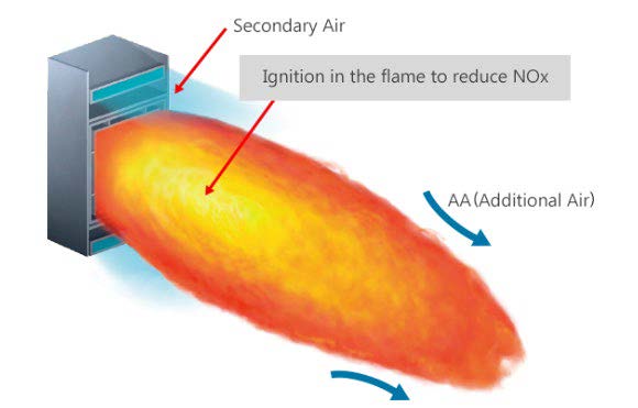
Note. Adapted from https://www.mhps.com/products/boilers/technology/low-nox-burner/index.html
Combustion reduction and burnout are achieved in three stages within a conventional low NOx burner. In the first stage, combustion occurs in a fuel rich, oxygen deficient zone where NOx formation takes place. In the second stage a reducing atmosphere follows where hydrocarbons react with the already formed NOx and reduce them to molecular Nitrogen. In the third and final stage of combustion an oxygen rich environment finalizes combustion of the fuel. Control of secondary air is important to ascertain full combustion, but not enough oxygen to regenerate NOx2.
However, source control by itself is not enough to meet NOx emission standards. Downstream technologies are also required to further reduce NOx. The two most common downstream measures to control NOx are Selective Catalytic Reduction (SCR) and Selective Non-Catalytic Reduction (SNCR). Both technologies convert NOx in the flue gas to inert molecular Nitrogen by reaction with ammonia. The different reactions for NOx reduction are shown below and is applicable for both SCRs and SNCRs.
4NO + 4NH3 + O2 → 4N2 + 6H2O (4)
2NO2 + 4NH3 + O2 → 3N2 + 6H2O (5)
NO + NO2 + 2NH3 → 2N2 + 3H2O (6)
There are process, efficiency and cost differences between the two technologies and due diligence is required to make a proper selection. The selection of NOx control systems needs to be done in coordination with the overseeing environmental agency.
3.2. Selective Catalytic Reduction (SCR)
SCRs are state of the art systems used to eliminate or reduce NOx emissions from the flue gas stream. In this process, ammonia (NH3) is injected into the flue gas stream to create a chemical reaction between NOx and NH3 forming inert Nitrogen molecules and water vapor as products. These chemical reactions are shown in equations 4-6. For the chemical reactions to occur, the gas needs to be between the optimum temperatures of 300°C and 400°C; therefore, the system is usually placed before the air preheater, at the exit of the economizer.
This technology uses a catalyst which facilitates the breakdown of NOx and increases the overall conversion efficiency. Most catalysts used in coal power plants consist of vanadium making up the active catalyst, and the substrate (or catalyst support) is usually made of titanium3. Active catalyst is finely dispersed across the support media. However, the final composition can consist of many active metals and support materials to meet specific requirements in each SCR installation. Typically, over 90% reduction in NOx can be achieved with the installation of a SCR6. SCRs are also a widely used technology in the off-gas treatment of large gas combustion turbines.
Figure 2. Schematic of a SCR process
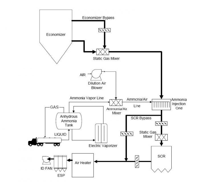
Note. Adapted from https://www3.epa.gov/ttn/ecas/docs/SCRCostManualchapter7thEdition_2016.pdf
SCRs are designed to handle dust loads and do not require dust capture equipment upstream of the process. The system is relatively easy to maintain and capable of stable operation. While the system offers high NOx control, it is capital cost intensive and requires considerable plant outage time for retrofit applications.
Figure 3. Selective Catalytic Reduction (SCR) System
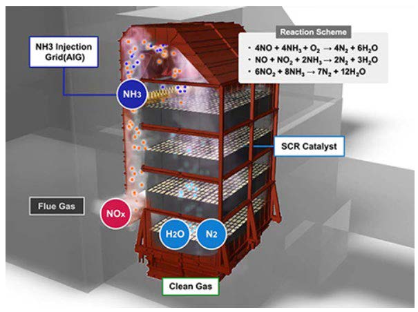
Note. Adapted from https://www.mhps.com/products/aqcs/lineup/flue-gas-denitration/
SCR capital costs vary by the type of unit controlled, the fuel type, the inlet NOx level, the outlet NOx design level, and reactor arrangement. Data collected on new installations between 2012- 14 indicated SCR costs ranged from $270/kW to $570/kW5. Typical operation and maintenance costs are approximately 0.1 cents per kilowatt-hour (kWh)5. Operating costs for SCR consist mostly of replacement catalyst and ammonia reagent, and while historically the catalyst replacement has been the higher cost, the reagent cost has become the most substantial portion of operating costs for most SCR. Since the gas pressure drops across the SCR system, the plant may also require ID fan modifications to compensate for the increased pressure loss.
3.3. Selective Non-Catalytic Reduction (SNCR)
While SCR is considered as the BACT, in certain applications, SNCR technology can be deployed at a relatively low capital cost. However, SNCR does not employ a catalyst and NOx reduction is typically a modest 30-50%4 for most systems. This technology utilizes atomizing nozzles to inject ammonia directly into the hot gas to chemically reduce NOx to Nitrogen and water vapor. Unlike the SCR, NH3 injection is at a much higher temperature window between 850-1,050°C4. The goal is to maximize NOx control performance while optimizing chemical utilization with low reagent consumption.
Figure 4. Schematic of SNCR Process
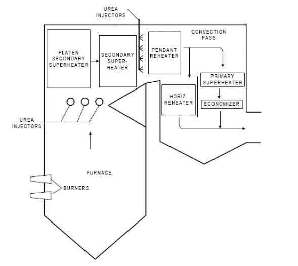
Note. Adapted from https://www3.epa.gov/ttnecas1/models/SNCRCostManualchapter_Draftforpubliccomment-6-5- 2015.pdf
Additionally, urea can also be used as a reagent for SNCR applications. Urea (NH2CONH2) is easier to handle and store than NH3. Hence, urea-based systems are more common than ammonia based deployments, but operating data reveals higher NOx reductions occur with ammonia reagent. This is mainly due to improper and incomplete gas mixing with urea injection compared to anhydrous ammonia. Urea dissociates into ammonia first and then reacts with NOx as shown in chemical reactions 4-6. The dissociation of urea to ammonia is as follows:
NH2CONH2 + H2O -> 2NH3 + CO2 (7)
Figure 5. Urea Based SNCR Process Schematic
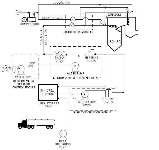
Note. Adapted from https://www3.epa.gov/ttnecas1/models/SNCRCostManualchapter_Draftforpubliccomment-6-5- 2015.pdf
The effect of temperature is critical for SNCR applications. Not only does temperature affect conversion efficiencies, but it can also have a debilitating effect if ammonia or urea is injected outside the recommended range. At lower temperatures NO and the ammonia do not react. Ammonia that has not reacted is called ammonia slip and can react with other combustion species, such as sulfur trioxide (SO3), to form ammonium salts. These salts can later form hard deposits on downstream equipment thereby reducing operating efficiencies. At higher temperatures ammonia decomposes to form more NOx.
SNCR is applied in a wide range of industrial processes, including cement and steel production. While not a BACT option for power plants, it is suited for areas under Reasonable Available Control Technology (or RACT) protocol. Retrofits are also much easier and require a small area for installation. Available data for Best Available Retrofit Technology (BART) analyses for 11 cement kilns indicates estimated NOx reductions for SNCR systems between 35 percent and 58 percent with a median reduction of 40 percent6.
The mechanical equipment associated with an SNCR system is simple compared to SCR and hence capital costs for SNCR installations are generally low. Based on available data, the installed capital cost of SNCR applications ranged anywhere between $5–20/kWe (kilowatt) for power generation units6. The absence of an expensive catalyst reduces CapEx requirements for both new systems as well as retrofits. Most of the cost of using SNCR is an operating expense. Reagent costs currently account for a large portion of the annual operating expenses associated with this technology. The annual cost of reagent purchase in $/yr is estimated using the reagent volumetric flow rate, the total operating time, and the unit cost of reagent. One of the bigger challenges with SNCRs is the stack emission of ammonia slip and this concentration is typically higher than SCRs due to larger injection rates. The temperature window at which SNCR typically operates plays a role in NH3 slip levels. Distribution of the reagent can be challenging especially in larger coal-fired boilers because of the long injection distance required to cover the relatively large cross-section of the boiler. Multiple layers are required to adjust to constantly changing boiler loads and this makes it challenging to fine-tune. Additionally, when urea is injected, large quantities of water are required, which can result in efficiency losses.
Depending on the type of process, PEC Consulting can help in the selection of the best control technology to help reduce NOx emissions. We conduct an objective analysis to select the most feasible and efficient option to meet overall process and environmental requirements.
References
- 1STEAM / Its Generation and Use, The Babcock & Wilcox Company, 42nd Edition 2. International Energy Administration, Clean Coal Centre, Clean Coal Technologies, “Low NOX Burners”, https://www.iea-coal.org/low-nox-burners/
- 2International Energy Administration, Clean Coal Centre, Clean Coal Technologies, “Selective Catalytic Reduction (SCR) For NOx Control”, https://www.iea coal.org/selective-catalytic-reduction-scr-for-nox-control/
- 3International Energy Administration, Clean Coal Centre, Clean Coal Technologies, “Selective Non-Catalytic Reduction (SNCR) For NOx Control”, https://www.iea coal.org/selective-non-catalytic-reduction-sncr-for-nox-control/
- 4International Energy Administration, Clean Coal Centre, Clean Coal Technologies, “Selective Non-Catalytic Reduction (SNCR) For NOx Control”, https://www.ieacoal.org/selective-non-catalytic-reduction-sncr-for-nox-control/
- 5Chapter 2, Selective Catalytic Reduction,
- 6https://www3.epa.gov/ttn/ecas/docs/SCRCostManualchapter7thEdition_2016.pdf 6. Chapter 1, Selective Noncatalytic Reduction, https://www3.epa.gov/ttnecas1/models/SNCRCostManualchapter_Draftforpubliccomm ent-6-5-2015.pdf
- 7Reeves, Claire E.; Penkett, Stuart A.; Bauguitte, Stephane; Law, Kathy S.; Evans, Mathew J.; Bandy, Brian J.; Monks, Paul S.; Edwards, Gavin D.; Phillips, Gavin (2002-12-11). “Potential for photochemical ozone formation in the troposphere over the North Atlantic as derived from aircraft observations during ACSOE”. Journal of Geophysical Research: Atmospheres. 107 (D23)
- 8https://www.mhps.com/products/aqcs/lineup/flue-gas-denitration/
About the Author(s)
Prasanna Seshadri, PhD
Dr. Prasanna Seshadri is an experienced engineer with strong background in process design, project engineering and management, technology and new product development for a wide range of energy conversion and environmental control processes used in power and other heavy manufacturing industries. He is Subject Matter Expert (SME) for solid fuel combustion, acid gas, and heavy metals emission control for thermal conversion systems and wastewater treatment. He has a BS in Chemical Engineering from the University of Madras, India, MS in Environmental Engineering and PhD in Energy Engineering from the University of North Dakota.
PEC Consulting Group LLC | PENTA Engineering Corporation | St. Louis, Missouri, USA
How can we help you? Get in touch with our team of experts.