Best Practices in Frac Sand Plant Design
By Thomas W. Hedrick
The sample project is a frac sand plant located in the beautiful hill country of Texas, U.S.A. It has been designed in two phases: the first one taking place now and the second phase to take place in the future. The latter will double the size of the plant to over 4 million tons per year, with logistics running 24 hours per day, 7 days per week.
An important starting point of all projects is permitting. Construction cannot start until permits are issued. A 3-D modeling presentation that demonstrates an environmentally friendly plant makes a better presentation for permitting meetings. Figure 1 is such a model. The border has earthen berms to hide the view from the passing public. The berms will be planted with native wild flowers and trees. Modeling will be used to prevent plant lights from distracting the passing public both in directionality and lamp shading.
Figure 1. Site Plan Viewed From Entry Road
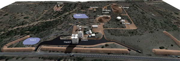
There are two interconnected water collection ponds along the left diagonal of the site. The centermost pond has a pumping station to recycle water back into the process. All aspects of the site are designed for maximum water conservation. Processing efficiency was benchmarked at about 50% of water used in other similar operations in the area.
In Figure 1, on the right side of the property, a deceleration lane was designed for queuing the trucks off of the public highway. The maximum utilization of existing trees helps blending the site into the natural topography of the area. The access road around the perimeter of the plant weaves in and out of these trees.
By rotating the model to a view from a passing car’s perspective, the site looks like Figure 2. The berm height is 15’; it is shown here without vegetation. The load-out silos are the tallest point on the property, and the dry screening plant is to the right of the silos. Using the model in this fashion, each neighbor will be able to see a rendering of the facility from their vantage point.
Figure 2. Motorist View From The Highway
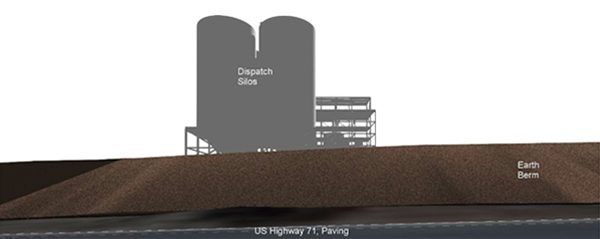
Figure 3. View From the Back of the Property.

Three-quarters of a million dollars was saved by placing the Primary Crusher in the pit rather than building retaining walls around the primary crusher pit. This area is on the right side of the rendering (see Figure 3). The trucks dump directly into the feed hopper. There is plenty of room for maintenance access around the equipment. Just to the left of the crusher is a creek bed. Traffic is not allowed across the creek, so crusher access will be from the right. The secondary screening plant is on the left side of the page, with minus ¾” feed to the extreme left.
The primary crusher circuit includes a vibrating grizzly to remove the fines and a Jaw Crusher set at 2”. This closed-side setting mates well with a vertical shaft impactor used as a secondary crusher.
The secondary screens are rated at 1,400 tph including the recirculation load. The traditional solution would be two 8’ x 24’ double-deck vibrating screens. The screen shown in Figure 4, a single 12’ x 24’ high horizontal impact screen for the same task, was evaluated. This eliminated a complicated feed section (for two screens, three conveyor belts, and a much larger building). Not counting electrical savings, the project saved over one million dollars and ended up with a highly reliable screen solution.
Figure 4. Ludowici Double-Deck Banana Screen

A common method to stockpile sand is by utilizing a radial stacking conveyor. One very easy way to increase the volume of stored material at little additional cost is by using a telescoping radial stacker. Figure 5 shows the original stacked volume (shown in lighter buff), which can be more than doubled by extending the stacker (shown in darker buff). A number of manufacturers offer telescoping radial stackers, which claim additional benefits of wind-rowing the storage to minimize segregation. Both stacking storage yards in this project utilize this technique.
Figure 5. Telescoping Radial Stacker

Attrition scrubbers are used to break up the sandstone into individual particles. Hydraulic cyclone separators are used along with a hydrosizer to capture the particle size desired (ASTM 16 mesh to ASTM 70 mesh); the rest is sent to spoils. A second scrubber circuit is used to liberate any final sticky sand. This plant uses a bucket wheel to dewater the product. Spoils are pumped back to a vacant quarry rather than returned with an overland conveyor. This plant operates with about 25% product reclaim. With both phases in operation, 16 million tons will be mined annually and 4 million tons of products will be reclaimed.
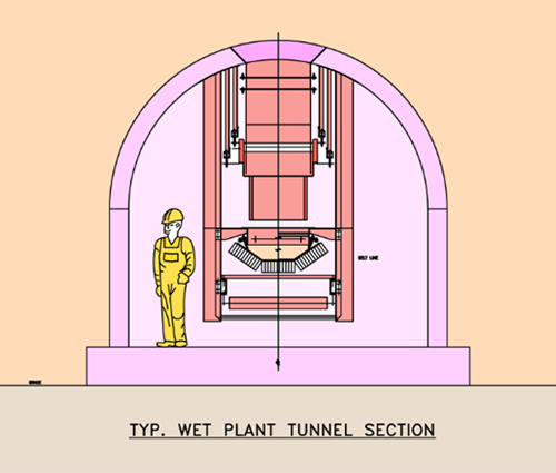
Figure 6. Wet Plant Tunnel Section
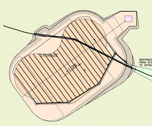
The wet storage pile contains the product sizes desired. Figure 7 shows an important step in the preparation for the reclaim tunnel. A percolation field draws down the moisture content. Typically without the field, the 13% moisture in the wet plant discharge will reach about 6% moisture by utilizing inventory management (using the drained or older sand before the newly processed sand). By utilizing the percolation field, the 6% moisture can be reduced to 4% moisture.
Another feature of the design is to use an arched tunnel (see Figure 6) rather than a rectangular tunnel section. The obvious advantage is that the water from the storage migrates around the tunnel rather than lying on the flat roof and ultimately collects inside the collection system. Dewatering feeders collect water from the tunnel and pipe it to the outside. The grade of the tunnel is 1% for positive drainage. Hanging the conveyors from the concrete tunnel makes cleanup much easier.
One last feature of the tunnel system is that the pile orientation is such that the wind blows along the pile 95% of the time rather than across the pile. The product sand is very susceptible to wind dune action. Pile orientation is a very important feature.
The wet pile area is underlay with an impervious membrane, which includes the low point of the pile to the collection pond (to the right in Figure 7). As much as possible, all process water is recycled.
Figure 7. Percolation Field Under Wet Storage
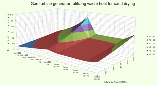
With today’s long range, low price outlook a natural gas generator may be used to generate both plant power and provide the energy from the turbine exhaust to dry sand in a rotary or fluid bed dryer. Payback depends on an agreement with the utility company and on the price of electricity. An analysis on this plant with moderate electrical costs the simple payback appears attractive (see Figure 8). Various models of Caterpillar generator sets were investigated (along the x-axis), since they are easily maintained by agreement with the local dealer, keeping ownership simple.
The graph includes various costs for natural gas ($3.00 to $5.00), and the resulting payback for the generator sets. The payback zone is a colored band over the several generator sets and given their costs (and switchgear plus installation) with the variation in gas costs.
Figure 8. Payback Analysis Based on Cost of Gas and Moisture Content of Sand
To properly evaluate the gyratory screening equipment, the cost of the building must be included. Issues of changes in structural support between various OEM schemes including the finished product screen tower were evaluated.
Four products are distributed by the red colored bucket elevators on the left to 6 silos of the dispatch storage. The flat floor of the concrete allows the use of one discharge equipment set on rollers such that it may be placed in multiple locations. The flat slab keeps costs lower. The typical steel bins on structural legs were engineered earlier in the project. As the client’s loading capacity increased, this became less of an option. One problem with multiple steel bins is that with complex conveyor systems distributing product at the roof level, structural supports become very complex. With concrete silos, the flat roof provides needed support wherever it may occur.
The silo set has two analyzer rooms at the upper loading floor for quick quality control analysis of each truck as it is loaded. An average of 240 trucks is loaded each day, 7 days per week. For peak loading, 6 lanes were chosen with 140’ long scales so that easy access is provided under all loading positions.
Provisions were made for flushing silos should QC reject product. This structure is the tallest of all the buildings and, as noted in Figure 2, is the main focal point a passer-by will see of the facility.
Figure 9. Silo Plan and Elevation Views

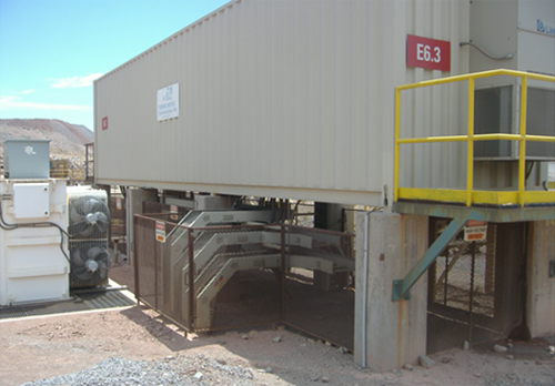
Prefabricated electrical rooms are very easy to fit into a project. As shown in Figure 10 the room is elevated to allow room for easy access with larger cables. The transformers can be easily located nearby and the rooms are provided with both cooling and pressurization to keep out the dust and sand. In this project, electrical rooms are divided and one part serves as the local control room for the operation of certain areas of the plant. For larger needs, multiple rooms can be joined. For other projects, electrical rooms have been elevated like the one pictured to the top of silos for easy modular controls.
Figure 10. Prefabricated Electrical Room
One feature of all projects that should be considered is the next phase. There is always a need to expand. Thinking about where the expansion goes, the access to the new phase should be considered right away. Electrical rooms need extra capacity and a location that is convenient to both phases. In this case, the permit application included the second phase emissions.
Another important feature of good design is to consider maintenance and access. For example, conveyors were hung from the tunnels for cleanup access. The transfer towers were constructed as slab-on grade with elevated slabs (because plants seem to buildup elevation over time) and k-bracing allowing bob-cat access for cleanup. Castigated s-section trolley beams (beams with punched holes in them for come-along anchoring) were specified. Each piece of equipment was checked for proper maintenance access. The use of roll-away chutes in front of multi-deck screens is recommended so that the crew that needs access for screen changes can roll away the chute work.
About the Author(s)
Thomas W. Hedrick
Mr. Hedrick, P.E. is a Senior Project Consultant at PEC Consulting Group. He specializes in materials handling, has been in manufacturing and engineering for 40 years, holds seven U.S. patents, and has written several dozen technical papers for various magazines and conferences around the world. Mr. Hedrick maintains a passion for excellence in client relations and project execution.
PEC Consulting Group LLC | PENTA Engineering Corporation | St. Louis, Missouri, USA
How can we help you? Get in touch with our team of experts.